> READ HANDS-ON-SOLDERING-CLASS
A Hands-On Soldering Class at the Maker's Space
A Hands-On Soldering Class at the Maker’s Space
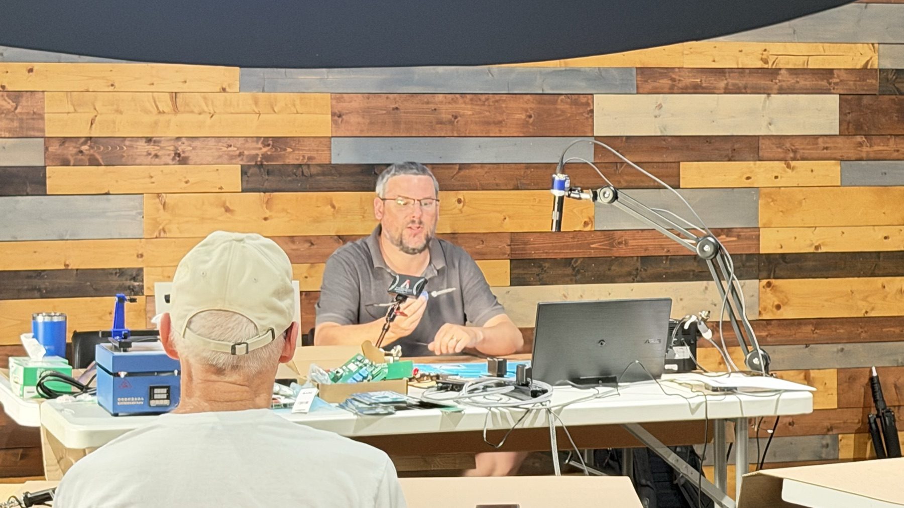
On Monday evening, I attended an electronic soldering class in the community room at Life Bridge Church in Fort Wayne. On the second Monday of each month, the room becomes The Maker’s Space, with a class that is open to the public and built around learning practical skills together.
This session brought out 15 students and one instructor, which was a great turnout for a hands-on electronics class.
A Shout-Out to W9TST
The class was taught by Brett Gilsinger, W9TST, a Fort Wayne amateur radio operator with an active General-class license. Brett has an extensive background in electronics, including designing his own printed circuit boards, and that experience showed throughout the evening.
He did not simply demonstrate a joint and turn everyone loose. He explained what was happening, why common mistakes happen, how to recognize them, and how to correct them. The class was well organized, easy to follow, and welcoming to people with different levels of experience.
The Project
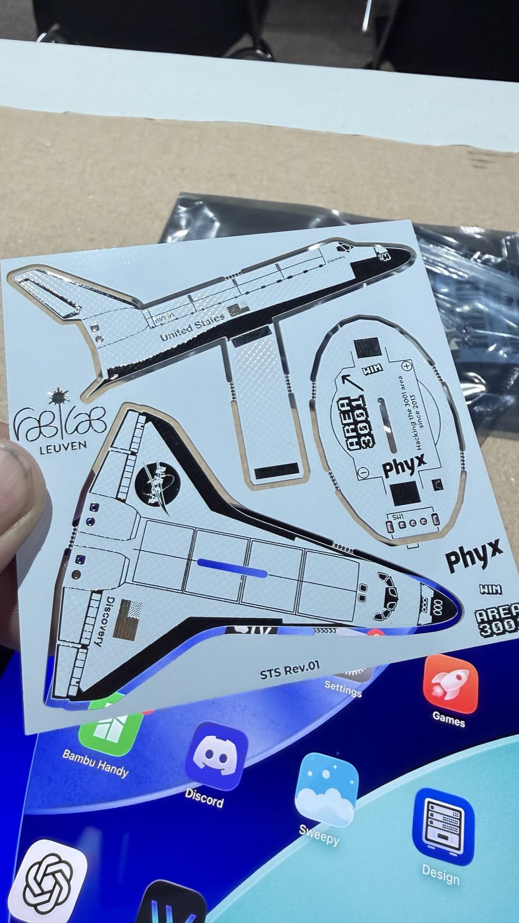
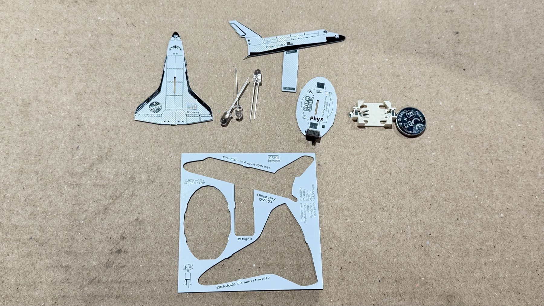
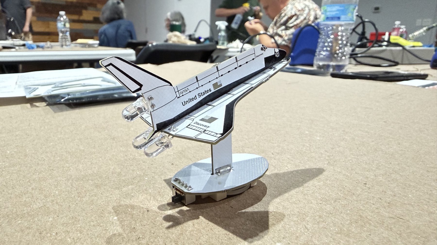
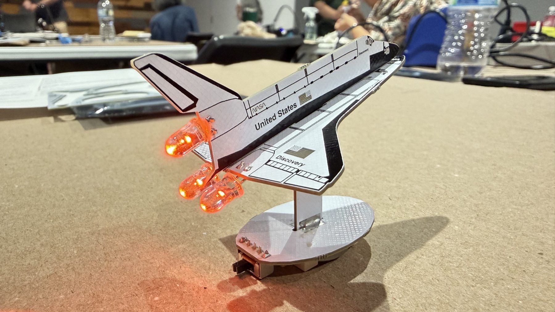
Everyone worked with the Space Shuttle Discovery Solder Kit by Phyx, sold by Adafruit as product 5414 and marked P5414A on the class kits. The kit uses several shaped circuit boards that assemble into a small standing model of the Space Shuttle Discovery. The LEDs at the engines light when the completed circuit is switched on.
It was a good class project because it combined ordinary through-hole solder joints with mechanical assembly. At the end of the evening, everyone had something recognizable and functional to take home.
Learning Why a Joint Works
Brett started with the fundamentals: checking the iron, keeping the tip clean and tinned, choosing an appropriate solder diameter, understanding flux, and recognizing how heat moves through a joint. One of the best explanations from the class was that solder wets metal; it does not glue it.
For a basic through-hole joint, the process was broken into five counts:
- Touch the iron to both the pad and the component lead.
- Give the heat a moment to move into the metal.
- Feed solder into the far side of the joint rather than directly onto the tip.
- Watch it flow around the lead and form a fillet.
- Remove the solder first, then the iron, and hold everything still while the joint cools.
The slides also covered how to identify good, cold, starved, excessive, bridged, and disturbed joints. That was valuable because making a connection is only part of the job; being able to inspect it matters just as much.
The Masking-Tape Method
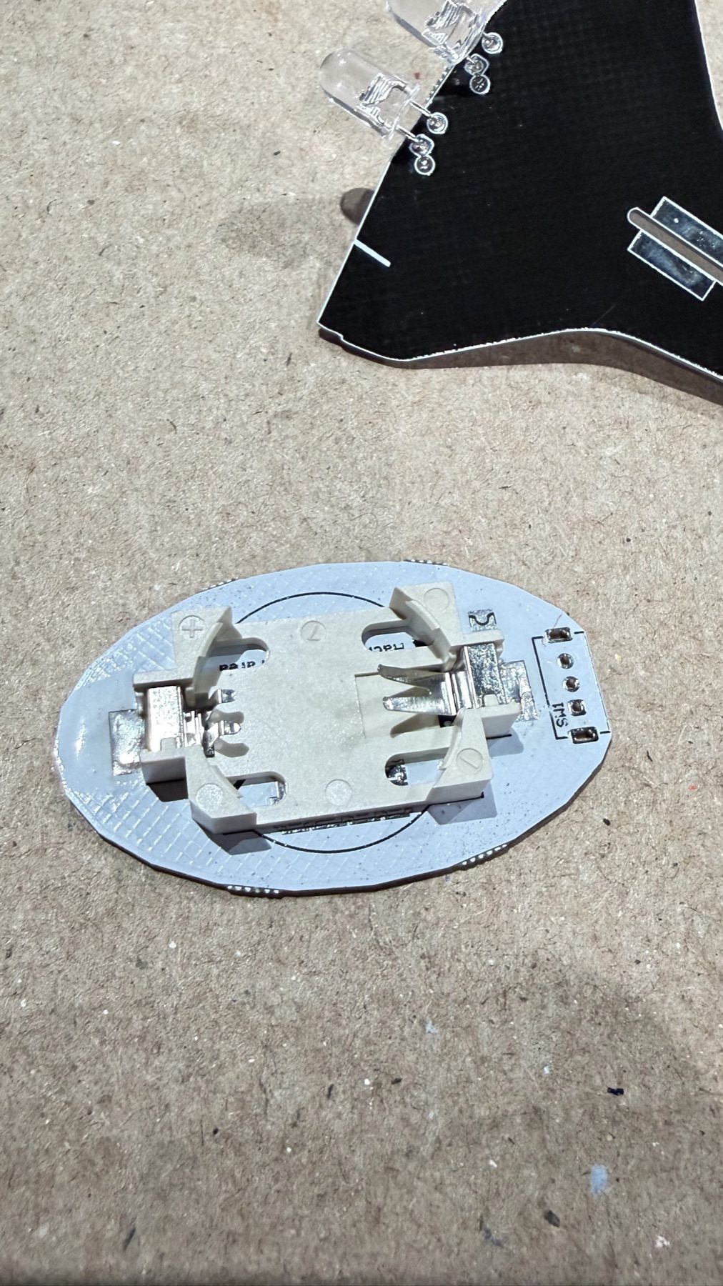
One technique from the class that I want to remember is using masking tape to hold components firmly against the board while soldering.
Do not fold or bend the component leads over after inserting them through the PCB. Folding the leads might hold the part temporarily, but it can make the component extremely difficult to remove later if it needs to be replaced.
Instead:
- Insert the component and tape it securely in place.
- Solder only the first pin.
- Remove the masking tape.
- Reheat that first joint while gently pushing the component until it sits flat against the PCB.
- Hold it in position and allow the first joint to cool.
- Solder the remaining pins.
If a joint needs to be reheated later, secure the component again with tape or another support first. Otherwise, the part can move or fall out as soon as the solder becomes liquid.
That is a simple process, but it produces a cleaner board and makes future repair much easier.
The Finished Shuttle
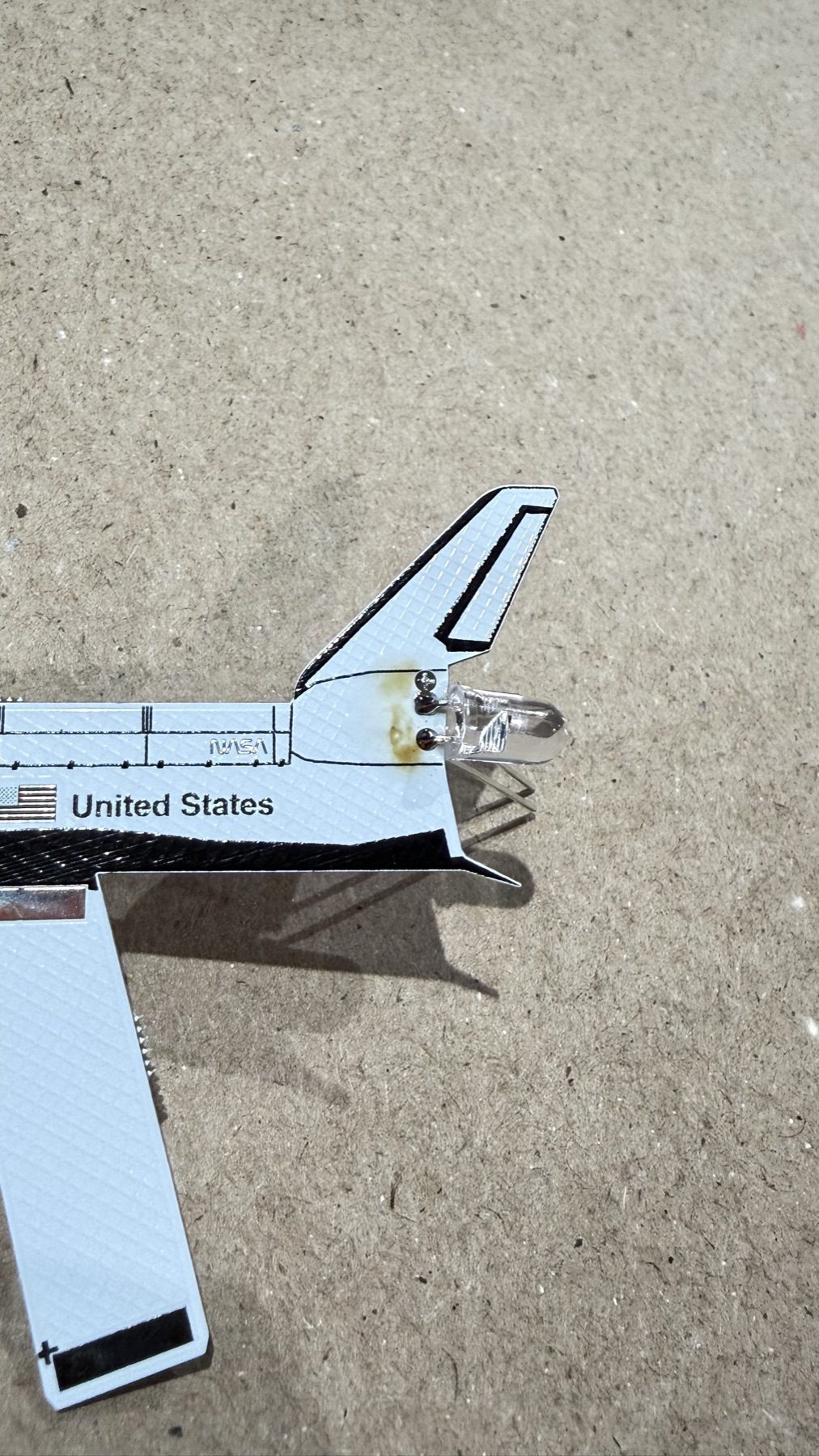
By the end of the class, the separate boards and small collection of parts had become a completed Space Shuttle Discovery model. Seeing the engine LEDs turn on was a satisfying final test that the solder joints, component orientation, and assembly were all correct.
Class Materials
Brett provided both a slide deck and a one-page set of take-home notes. They cover tip care, solder types, flux, the five-count soldering motion, joint inspection, practice exercises, and suggestions for what to buy next.
The class was practical, well taught, and a good example of what a community maker space can offer. Brett deserves a big thank-you for putting the material together, sharing his experience, and spending the evening helping everyone build confidence at the soldering bench.
If you are near Fort Wayne and interested in future classes, check The Maker’s Space event page for upcoming activities.